The incubator "set point" must be determined empirically before use with cultures.
- At the microscope:
- Position the culture chamber or culture dish on the microscope stage exactly as it will be during use.
- Focus (approximately) the objective and condenser.
- Cement the small surface temperature probe to the coverglass of the culture chamber.
If using a culture dish, place the probe inside the dish. Either method will indicate the temperature of the growth area.

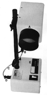
- Position the incubator so that the output tube (A) is 15 to 30 cm from the specimen with an angle of declination of about 30 degrees from horizontal. Note that the temperature stability is higher and the power requirements are lower when the output tube is closer to the specimen. (Adjustment knobs are located in the back of the upper unit. Take care and only tighten them enough to hold the position.)
- Position the tip of the control thermistor (B) so that it protrudes about 3 cm inboard from the tube rim.
- Connect the cable (C) coming from the upper unit to the connector (D) on the back of the lower unit.
- Plug the power cord (not shown) into a properly polarized and grounded 115 Volt receptacle only.
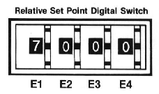
- Set the relative set point digital switch (E) to 6000 and turn on the incubator.
- Adjust temperature: The relative set point switch is equipped with four thumbwheels each corresponding to different levels of temperature adjustment - gross (E1), fine (E2), very fine (E3),extremely fine (E4).
From left to right, each thumbwheel after E1 (gross) provides an adjustment 1/10th the value of the preceding thumbwheel.

To calibrate the temperature setting: Begin with the "gross" (E1) adjustment wheel and increase or decrease the setting until the temperature reading is as close as possible to the desired temperature without exceeding it.
Moving from left to right (E2 - E3 - E4), continue fine adjustment with the remaining three thumbwheels until the required temperature reading has been reached. In each case, slowly adjust only until the temperature reading is as close as possible to the desired temperature without exceeding it.
Temperature stabilization requires several hours due to the heat sink effects of the stage, chamber, and condenser. The voltmeter on the bottom unit is provided only as an aid to determine the stability of the controller.
- When the desired temperature has stabilized mark the bench top with the outline of the incubator to assure that the exact positioning will be maintained.
Note: Any change in the position of the incubator may result in the need to readjust the temperature.
Calibration of the NEVTEK ASI 400 Air Stream Incubator for use in other laboratory procedures.
- Position the incubator so that the output tube (A) is approximately 30 cm from the specimen.
Adjust the angle of the head so that the air stream is focused directly on the specimen. (For warmer than normal requirements, position the incubator closer the the specimen.)
- Place the temperature probe directly on the surface area to be stabilized.
- Follow items 3 through 8 as noted above.
The NEVTEK ASI 400 Air Stream Incubator has been designed to provide optimal performance in a wide range of environments. However, any precautions taken to protect the system from gross humidity changes or strong drafts will improve performance.
Use of the NEVTEK ASI 400 under conditions of strong drafts an/or large room temperature variations
In either of the above calibration setups the control thermistor (B) may be removed from the output tube (A) rim and secured near the specimen on the microscope stage. This will result in the highest temperature stability under these conditions, however; extreme care must be taken to insure that the control thermistor remains in the air stream at all times. Even a hand in the wrong place will disturb the temperature. Expect the number on the relative set point switch (E) to be much less for the same temperature in this configuration.
Safety Features
The following safety features have been built into the unit to assure long life and optimal performance:
- Magnetic high speed circuit breaker switch.
- Long life impedance protected fan.
- Temperature limit fuse for the heater element.
In the event the airstream is interrupted or the control thermistor is not in the airstream, overheating will occur. The temperature limit fuse is a one time only cutoff device, that once triggered must be replaced. Spare thermal cutoff fuses are provided with each incubator. Beginning with serial number 549 the spare temperature limit fuse is located under the grounding screw (green wire) in the upper chamber. For your safety be certain to retighten this screw if the spare fuse is used!
Replacement of Temperature Limit Fuse
- Unplug the unit from the line voltage.
- Remove the upper unit cover by removing the four button head socket screws.
- Remove the two screws holding the fuse (inside the upper unit on the heater bracket).
- Remove the spent fuse and replace.
- Reassemble the upper unit.
Incubator Maintenance
The NEVTEK ASI 400 Air Stream Incubator was designed and constructed to provide years of trouble free continuous service with little maintenance. Routine dusting or cleaning with a mild detergent and water is recommended only to maintain the appearance of the unit. The air filter should be removed when dirty and cleaned with water and mild detergent.
Note:Accurate temperature determination requires the use of a temperature indicator and a small surface temperature probe. Omega Engineering sells a number of appropriate instruments such as the HH40 series Ultra-High-Accuracy Handheld Thermistor Thermometer and a ON-409-PP Attachable Surface Temperature Probe. Another possible instrument is the HH804U High Accuracy RTD Input Thermometer along with a HSRTD Series sealed probe or a SA1-RTD surface mount probe.


